Case study · Functional part · Design for 3D printing
A load-bearing monitor arm extension, printed in standard PLA
A 120 mm extension for a monitor arm pole, made in a material whose strength alone is marginal for a part in permanent bending. The strength came from geometry, print orientation and process settings, checked by calculation.
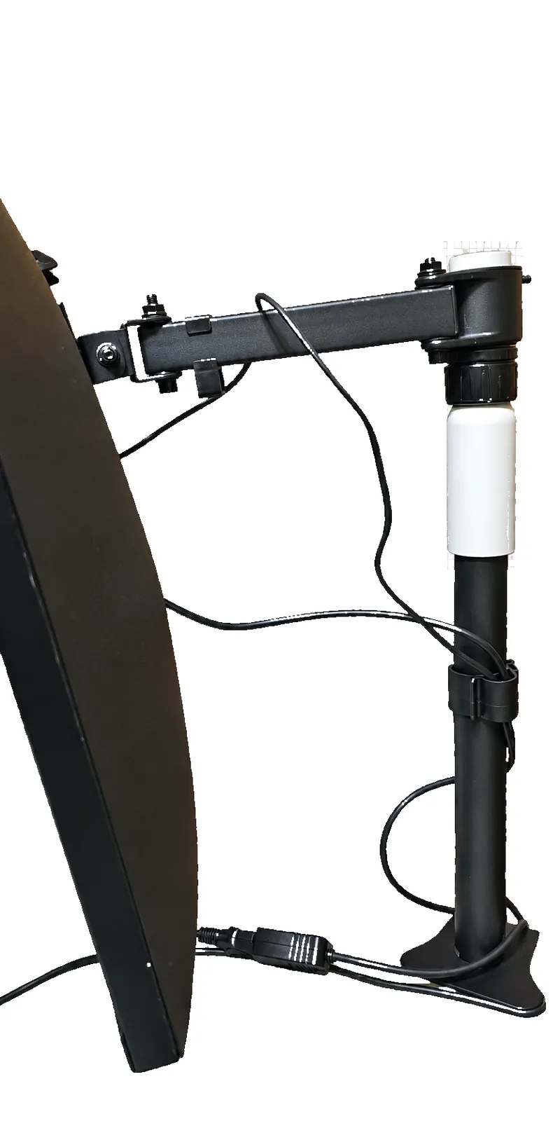
Raise the monitor at least 100 mm, without touching the mount
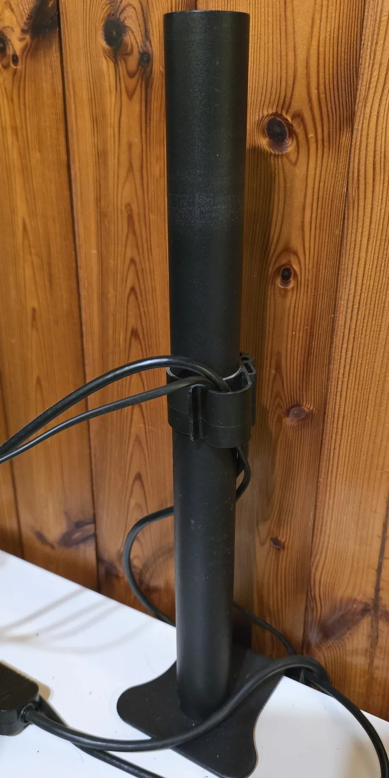
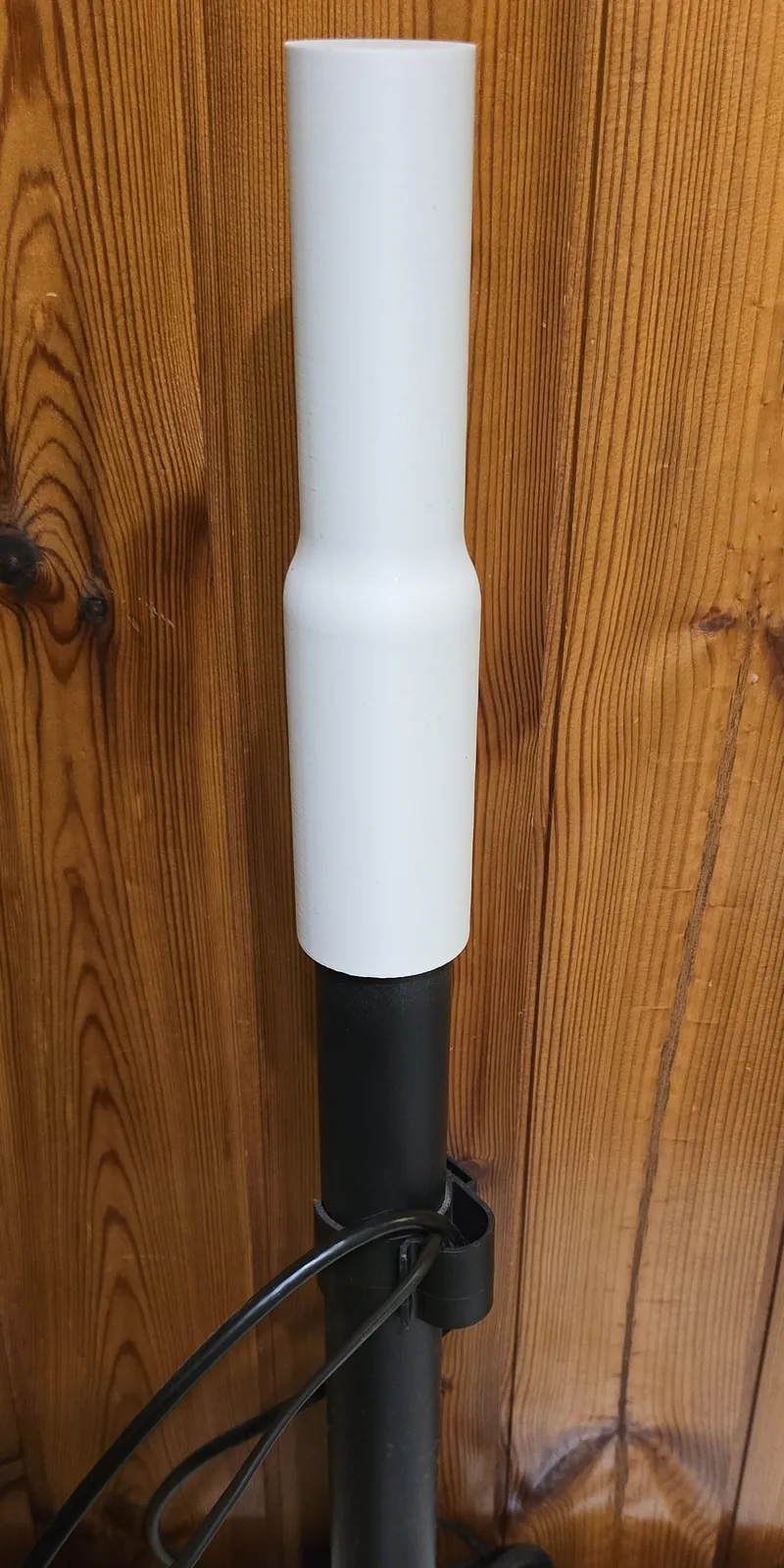
A 28" monitor on a single-arm desk stand sat too low, because the stand's steel pole was too short. The task was an extension that slides over the top of the existing pole and takes the arm's collar on its upper end, with no changes to the arm, the pole or the base.
The extension had to be made in standard PLA. On its own, that material doesn't give a comfortable strength margin for a part that carries a permanent load, so the shortfall had to be made up through design.
Requirements
The load is bending, and that's where printed PLA is weakest
It's easy to think of a pole extension as carrying weight straight down. It doesn't: the monitor hangs off the arm like a lever, so the pole carries a bending moment along its full length below the arm, including through the extension.
- Layer bonds. Printed upright, the bending stress runs across the layer lines, the weakest direction of any FDM part.
- Creep. Under a permanent load, PLA slowly deforms over weeks and months. A pole that gradually leans is the typical failure.
- Brittleness. PLA cracks suddenly rather than bending first, so sharp corners and overloads have to be designed out.
- Precise fits. The pole and the arm's collar are steel parts with fixed sizes, and printed holes come out undersize, so clearances must be designed in.
A dual-wall socket that grips the pole from both sides
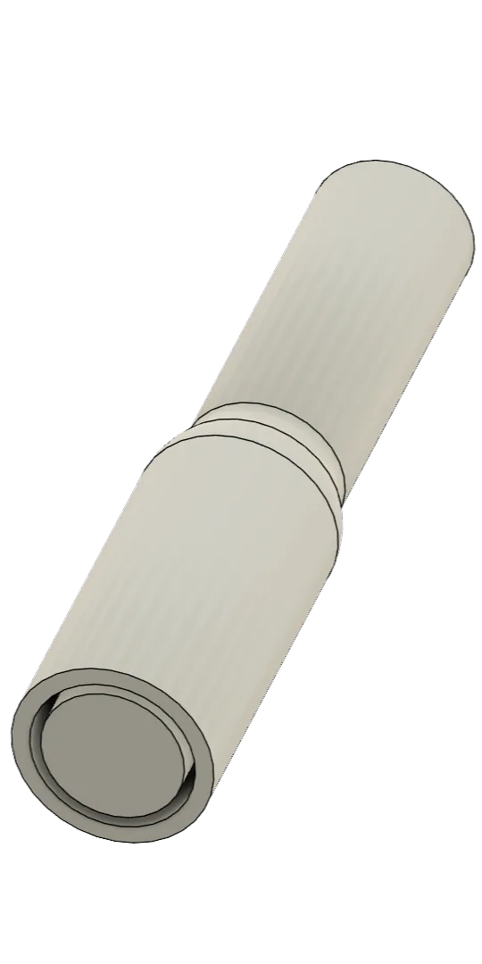
The extension is a single printed part. At its lower end, the steel pole's wall slides into a deep annular slot between an outer sleeve and a central post, so it is supported on its inside and outside faces and cannot rock. Below the slot the part is solid, and it steps down to the spigot through two large R20 blends instead of a sharp shoulder. At the upper end, the solid Ø35.45 mm spigot matches the pole's diameter, so the arm's collar fits it exactly as it fitted the original pole.
Design features
Peak stress about 2.6 MPa: more than seven times below short-term failure
The critical section is the solid Ø35.45 mm spigot just below the arm's collar: it has the smallest diameter and carries the full bending moment. The monitor weighs 5 kg (manufacturer specification); the arm's own weight was taken as 1.5 kg acting at 100 mm.
| Step | Calculation | Result |
|---|---|---|
| Bending moment | M = 5 × 9.81 × 0.18 + 1.5 × 9.81 × 0.10 | 10.3 N·m |
| Section modulus | Z = π × 35.45³ / 32 | 4374 mm³ |
| Nominal stress | σ = M / Z = 10 300 / 4374 | 2.4 MPa |
| Peak stress at the shoulder | Kt ≈ 1.1 (Peterson, stepped shaft, D/d = 1.24, r/d = 0.56; rounded up) → 1.1 × 2.4 | 2.6 MPa |
| Axial compression | about 64 N total weight over the spigot section | 0.07 MPa |
| Socket bearing | moment reacted over the 70 mm engagement, about 150 N each end | ≈ 0.4 MPa |
Assessment
Sensitivity to arm reach
| Reach to monitor centre | Moment | Peak stress | Status in PLA |
|---|---|---|---|
| 180 mm (as installed) | 10.3 N·m | 2.6 MPa | Acceptable |
| 300 mm | 16.2 N·m | 4.1 MPa | Acceptable, limit of use |
| 375 mm | 19.9 N·m | 5.0 MPa | At the creep limit |
| 450 mm | 23.5 N·m | 5.9 MPa | Not acceptable |
The layer-bond strength is a typical value for printed PLA, not a measurement of this specific filament.
Getting the strength from the printer, not the material
Rather than switching to a stronger material, the remaining margin came from how the part is printed.
| Setting | Value | Why |
|---|---|---|
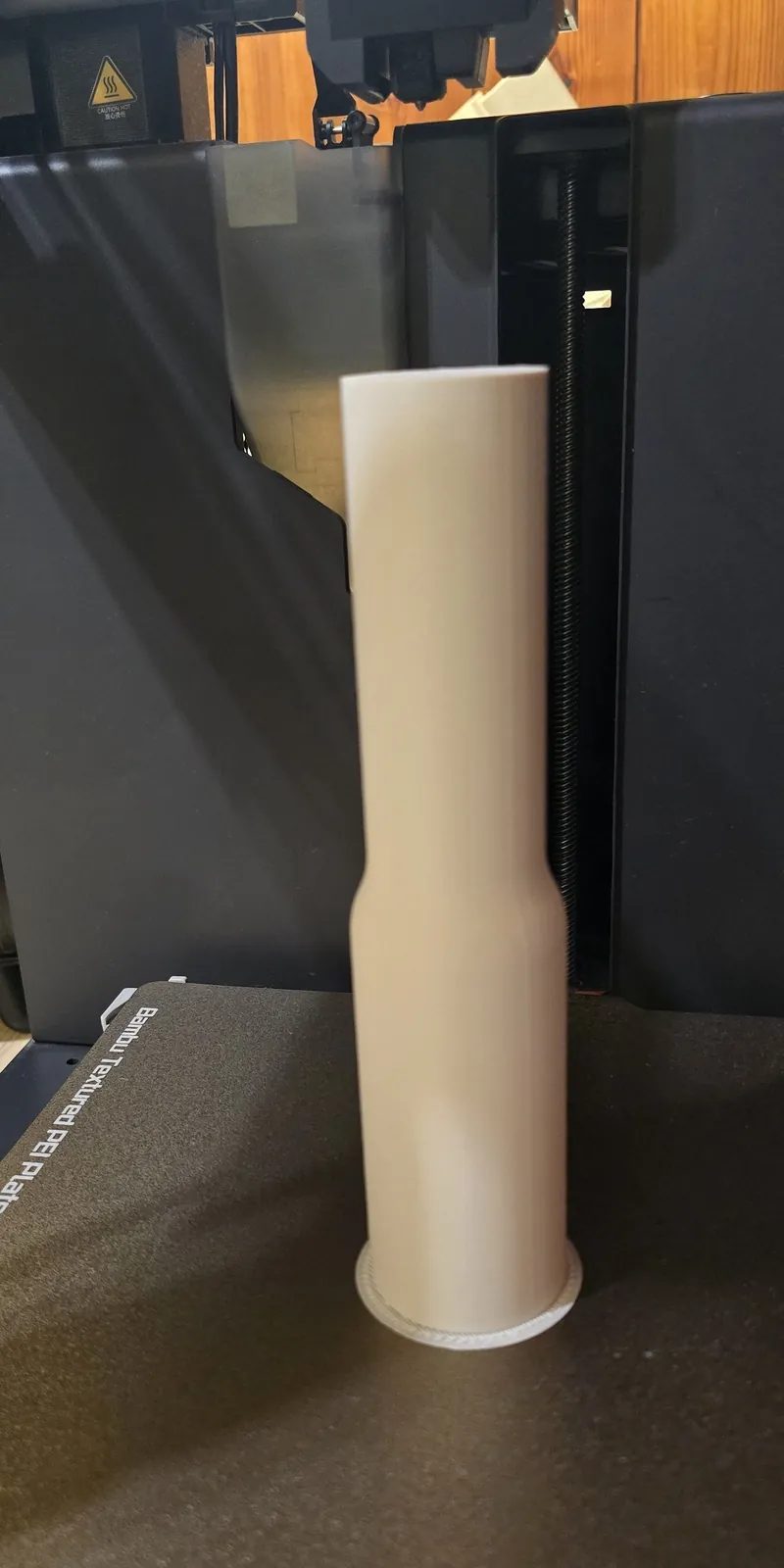
| Orientation | Upright, socket end on the bed | Round, accurate bores; no supports; the sleeve's hoop stress runs along the layers |
| Wall loops | 8 | In bending, the outer shell carries most of the stress |
| Infill | Gyroid, 60–100% | A near-solid core reduces creep; gyroid is strong in every direction |
| Top/bottom shells | 5 layers | Solid transitions at the socket bottom and the shoulder |
| Nozzle temperature | 225–230 °C | Stronger layer bonding without losing dimensional accuracy |
| Plate temperature | 55 °C, textured PEI | Reliable adhesion for a 190 mm tall part |
| Brim | 5 mm, outer only | Stops the tall, narrow part rocking or lifting |
A steel core, an M16 threaded rod through the full length, was evaluated as an upgrade. It would carry the bending in steel and remove the reach limit, and remains the route for heavier monitors or longer arms.
A design that states where it stops
- Keep the monitor centre within about 300 mm of the pole.
- Keep the part away from direct sunlight and heaters: PLA softens at about 55–60 °C.
- Check the pole for lean after one week and after one month.
- For a heavier monitor or a longer reach, use the steel-core version.
A 120 mm extension in standard PLA, sized by calculation
The result is a single printed part that adds 120 mm to the pole, carries the monitor within a defined reach and fits the existing pole and arm with no modifications.
The project shows how we approach functional printed parts: identify the real load, find the critical section, and use geometry and process settings to close the gap a material leaves, while being clear about the limits of the result.
Services behind this project
Need a functional part sized for its load?
Tell us what the part has to carry. We design it, check it by calculation and print it.
Request a quote →